
High-Speed PM Rotor Retaining Sleeve Selection: Interference Fit, Eddy Current Loss, and Material Trade-offs
High-speed PM rotor retaining sleeve selection: compare interference fit, eddy current loss and material trade-offs. Use the checklist to prepare your OEM RFQ.
High-speed permanent magnet rotor retaining sleeve selection requires balancing three coupled engineering constraints: mechanical hoop stress under centrifugal loading, parasitic eddy current heating caused by stator harmonics, and thermal expansion mismatch between the sleeve and brittle magnet segments. A strong sleeve can still restrict heat removal, while a conductive alloy can introduce additional rotor loss. Specify the coupled electromagnetic, structural, and thermal assembly rather than picking a material by name.
Published and reviewed: November 8, 2026. Scope: preliminary engineering screening and RFQ preparation for global motor design engineers, turbomachinery OEMs, EV powertrain developers, and industrial procurement teams considering surface-mounted permanent magnet (SPM) rotors. This guide focuses on high-speed applications, often above 20,000 rpm; rotor radius determines tip speed, so RPM alone does not establish sleeve suitability. Numerical examples are illustrative calculations, not measured MagAtom product results or approved design limits. Production release requires application-specific stress, electromagnetic, thermal, and rotordynamic validation, plus an agreed proof-test plan. Destructive burst testing is a separate qualification decision, not a test for every production rotor.
Sintered neodymium-iron-boron (NdFeB) and samarium-cobalt (SmCo) magnets provide strong air-gap fields but are brittle and relatively weak in tension. They should not be treated as ductile structural rings. A retaining sleeve, also called rotor banding or a retention sleeve, introduces compression to help prevent magnet cracking or lift-off. The sleeve rotates with the magnets; a stationary containment shell has different pressure and loss requirements.
To initiate a sourcing review, provide your rotor drawing, speed range, target air gap, thermal boundaries, and quantity plan through the MagAtom engineering contact form. The sections below explain the evidence to request before approving an assembly.
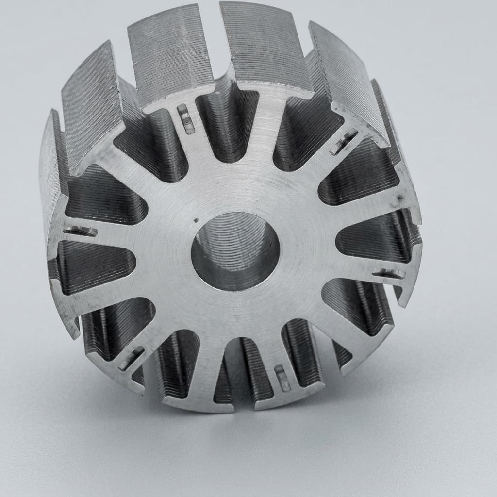
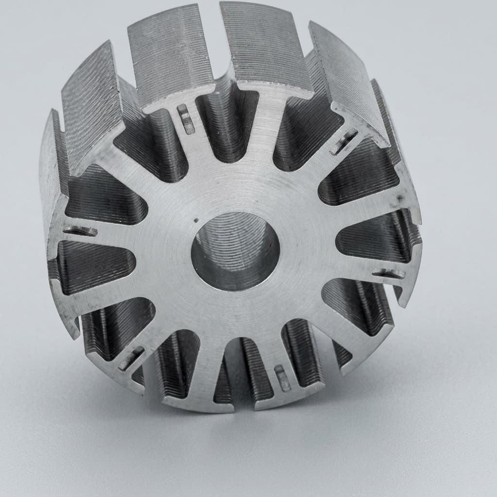
Product-family image of a laminated rotor core. It does not show a completed sleeved SPM rotor or certify a material grade or speed rating. Figure 1 explains the conceptual retention layers.
1. Operating physics and mechanical pre-stress fundamentals
At standstill and assembly temperature, the retaining sleeve exerts compressive pressure on the magnet assembly. As speed rises, centrifugal deformation changes the interference and interface pressures. Heating changes them again. Check cold start, hot running, shutdown, and the specified overspeed condition rather than analyzing one nominal point.
Why positive contact pressure matters
For a design that relies on maintained compression, specify contact pressure above an agreed minimum at each required interface throughout the operating envelope. The magnet-to-hub and sleeve-to-magnet pressures are different quantities. A positive pressure at the outer surface does not prove that the inner interface remains closed.
The residual pressure target must come from contact analysis, magnet strength, torque transfer, coating behavior, and tolerances. There is no universal 2–5 MPa acceptance value. Loss of contact can lead to fretting, adhesive overload, magnet movement, and imbalance, but it does not by itself prove immediate sleeve rupture. Adhesive strength and temperature limits must be taken from the qualified adhesive and cure process.
Centrifugal hoop stress in a rotating sleeve
For a freely rotating thin ring, a useful self-stress screening relationship is:
σ_self = ρ × v², with v = ω × r_mean and ω = 2π × rpm / 60.
Use density in kg/m³ and speed in m/s to obtain stress in pascals. At an illustrative mean-ring speed of 250 m/s:
- Inconel 718 at an assumed density of 8,190 kg/m³:
8,190 × 250² = 511.9 MPa. - Titanium alloy at an assumed density of 4,430 kg/m³:
4,430 × 250² = 276.9 MPa. - CFRP at an assumed laminate density of 1,550 kg/m³:
1,550 × 250² = 96.9 MPa.
These calculations isolate the density penalty. They omit magnet loading, assembly preload, temperature, end effects, and stress concentrations. A lower self-stress does not establish a rotor speed rating. Composite hoop ultimate strength must not be compared directly with metallic yield strength as if both were usable design allowables.
2. Rotor cross-sectional architecture and stress distribution
Figure 1 is an unwrapped radial layer schematic, not to scale. From the shaft outward, the layers are the hub, magnet segments, retaining sleeve, mechanical clearance, and stator bore. The outward arrows indicate magnet centrifugal loading; magnetic flux crosses the sleeve and air gap. Both contact interfaces require separate checks. On narrow screens, scroll the diagram horizontally to read its labels.
Figure 1: High-Speed SPM Rotor Layers, Retention Forces, and Harmonic Heat Sources
3. Lamé thick-wall equations and interference fit sizing
Define the fit convention before exchanging dimensions. Radial interference δr is half the diametral interference δD: δr = δD / 2. Mixing them produces a factor-of-two preload error. Record the inspection temperature and whether coating and adhesive thickness are included.
For an isotropic, linear-elastic sleeve under internal contact pressure p and negligible external pressure, the pressure-induced hoop stress at its inner bore is:
σ_hoop,pressure(ri) = p × (ro² + ri²) / (ro² − ri²).
Here ri and ro are the sleeve inner and outer radii. Contact compatibility can be written as p = δr / (Cs + Cc), where Cs and Cc are radial displacement-per-pressure compliances of the sleeve and core assembly. For an ideal plane-stress sleeve:
Cs = (ri / Es) × [(ro² + ri²) / (ro² − ri²) + νs].
Es is sleeve elastic modulus and νs is Poisson ratio. Determine Cc from the actual hub, magnet segments, bond layers, and contacts. A hollow homogeneous cylinder is not an adequate replacement for every segmented magnet-and-shaft assembly. For CFRP, use orthotropic laminate stiffness and a suitable composite failure assessment rather than applying isotropic Lamé equations unchanged.
Add rotation and thermal deformation through a compatible assembly model; contact pressure at rest is not necessarily the pressure at speed. For metals, assess the full stress state, fatigue, and temperature-dependent yield allowable. For composites, check hoop strain, transverse stresses, interlaminar failure, manufacturing defects, and life-dependent knockdowns. Safety factors and overspeed margins belong in the agreed design basis, not in a universal blog prescription.
4. Thermal expansion mismatch: relaxation vs. overstressing
For equal component temperatures and an idealized axisymmetric fit, a useful first screen is:
δr(T) ≈ δr,0 + ri × (αcore,eff − αsleeve) × ΔT.
The effective core expansion includes the hub and constraints, not just a handbook value for the magnet. NdFeB expansion is directional, and the magnetization/orientation direction can differ from the rotor radial direction. SmCo behavior also depends on grade and orientation. Obtain the relevant material data rather than assigning one radial coefficient to every magnet.
If the sleeve expands faster than the effective core, heating tends to reduce interference. If the effective core expands faster, heating tends to increase it. Different sleeve and core temperatures require separate thermal terms. Centrifugal expansion and changes in material stiffness must then be included to predict contact pressure.
Engineering implications for procurement
- Metal sleeves: check whether the hot condition loses preload and whether cold assembly or cold storage creates excessive stress. Increasing cold interference is only acceptable if magnet compression, coating damage, sleeve stress, and assembly feasibility also pass.
- Composite sleeves: low hoop expansion can increase hot preload in some assemblies, but it does not justify a small cold fit without analysis. Request resin glass-transition data, hot/wet laminate properties, creep and fatigue allowables, and the validated service-temperature margin. A single margin below Tg is not a universal release criterion.
5. Electromagnetic eddy current losses and harmonic shielding
In ideal synchronous operation, the fundamental field is stationary relative to the rotor. Stator slotting, winding space harmonics, and inverter current harmonics produce time-varying fields in the rotor frame and can induce losses in the sleeve, magnets, and hub.
Calculate resistive heating from the current distribution: P = ∫(J² / σe) dV, where J is induced current density and σe is electrical conductivity. A trend such as loss increasing with harmonic frequency squared applies only within its field and current-path assumptions. It cannot produce absolute watts without geometry, field amplitudes, skin effect, and end effects.
A metal sleeve may shield the magnets while generating its own heat. Higher resistivity does not guarantee a proportional reduction in total rotor loss because changing shielding changes the field reaching the magnets. Compare sleeve loss plus magnet loss plus hub loss, then include windage and the available cooling path.
CFRP is electrically anisotropic, not a perfect insulator. Carbon fibers conduct along their length, and winding architecture and inter-fiber contacts affect current paths. Evaluate conductivity in the relevant directions. Magnet segmentation or a separate shielding layer may help, but the segment insulation, shield heating, and total temperature rise need validation.
For a published example of the coupled method, Du et al., Energies 15(13), 4606 compare sleeve choices in a particular 105 kW, 36,000 rpm motor. Its selected sleeve thickness and cooling conditions are specific to that machine, not transferable material ratings.
6. Comprehensive sleeve material comparison matrix
Use these six candidates as a shortlist. The table deliberately avoids universal tip-speed ceilings and loss ratios: grade, heat treatment, laminate construction, geometry, and temperature determine the usable properties. Obtain traceable data for the delivered condition before calculating margin.
| Material candidate | Mechanical selection issue | Electromagnetic issue | Thermal issue | Assembly route | Evidence to request |
|---|---|---|---|---|---|
| CFRP hoop-wound laminate | Low density and strong hoop direction; transverse and interlaminar limits remain | Anisotropic conductivity; assess sleeve and magnet losses | Radial heat removal and resin service limit can govern | Qualified press-fit or direct winding | Laminate allowables, winding schedule, resin/cure record, defect limits |
| Titanium Grade 5, Ti-6Al-4V | Lower density than nickel alloys; yield and fatigue depend on condition | Conductive; shielding and loss require the actual harmonic spectrum | Check fit relaxation and heat-removal path | Controlled metallic shrink-fit | Exact grade and product form, heat treatment, hot strength and resistivity |
| Inconel 718, UNS N07718 | High-strength candidate; density adds substantial self-stress | Conductive sleeve can shield magnets while dissipating heat | Check core/sleeve expansion and complete assembly temperature limit | Controlled metallic shrink-fit | Condition-specific material certificate, strength/CTE curves, fit analysis |
| High-strength austenitic stainless, e.g. XM-19 | Strength and permeability depend on processing | Conductivity and magnetic permeability affect loss | Expansion mismatch can reduce preload | Machined shrink-fit | Exact material condition, permeability, temperature-dependent properties |
| Beryllium copper, e.g. C17200 | Dense; strength depends on temper | High conductivity can provide shielding but also changes sleeve heating | Potential heat-spreading benefit needs an assembly model | Qualified machined fit | Temper certificate, total-loss model, supplier machining controls |
| Glass-fiber composite, e.g. S-glass/epoxy | Lower hoop stiffness can require greater thickness | Glass fibers are insulating; check the complete laminate | Resin limit and low radial heat transfer remain | Qualified winding process | Laminate stiffness/strength, cure record, required air-gap allowance |
Grade clarification: Ti-6Al-4V ELI is commonly designated Grade 23; it should not be specified interchangeably with Grade 5. A carbon-fiber trade name likewise does not define the cured sleeve strength. Specify the finished laminate, fiber fraction, winding angle, cure, and inspection criteria.
7. Deep-dive trade-off analysis: CFRP vs. Titanium Gr5 vs. Inconel 718
Carbon fiber reinforced polymer (CFRP)
CFRP deserves early evaluation when low density and a thin retention layer are priorities. A thinner sleeve can preserve magnetic performance, but the resulting magnet radius, shaft stiffness, and rotor modes still require analysis. There is no universal speed above which CFRP becomes mandatory.
Its thermal resistance can make heat extraction difficult when the magnets generate appreciable losses. Compare radial cooling through the sleeve with conduction through the hub and rotor ends. Resin Tg alone is insufficient: the usable allowable also depends on temperature, moisture, dwell time, fatigue, and the qualified manufacturing process. Do not use fiber tensile strength as the sleeve design allowable.
Titanium Grade 5
Titanium is a candidate when a metallic assembly route and lower rotating density are valuable. It still incurs self-stress and harmonic loss. The final wall thickness must satisfy mechanical margin while preserving magnetic gap, bearing loads, and rotor stiffness.
Compare actual conductivity, thermal expansion, hot strength, and machining capability for the specified condition. A resistivity comparison alone cannot promise a fixed percentage loss reduction. Reject a candidate if the combined pressure, rotation, thermal, and fatigue checks fail, rather than using a generic 200–220 m/s ceiling.
Inconel 718
Inconel 718 is worth considering where the specified alloy condition, temperature capability, and environmental compatibility suit the assembly. Its greater density increases self-stress, while thermal expansion can reduce preload against a cooler or lower-expansion core.
The nickel alloy's standalone temperature capability does not set the rotor operating temperature. Magnet irreversible demagnetization, adhesive, coatings, bearings, and cooling may impose much lower limits. Request the actual material condition and application-specific compatibility evidence; do not infer corrosion or hydrogen-service approval from the alloy name.
8. Failure modes and structural risk mitigations
These are potential failure mechanisms to address in the control plan, not reported MagAtom field incidents. A vibration change alone does not identify its root cause.
| Failure mode | Trigger mechanism | Possible indicator | Prevention and verification |
|---|---|---|---|
| Magnet cracking or lift-off | Inadequate retention, excessive local stress, or interface opening | Vibration change, debris, or flux change | Evaluate both interfaces and magnet stress over the full speed/temperature envelope |
| Thermal fit relaxation | Sleeve/core thermal growth differs | Temperature-dependent movement or vibration | Use separate component temperatures, tolerance extremes, and hot-property data |
| Composite matrix or interface damage | Excess temperature, creep, defects, or press-fit damage | Delamination, OD change, or loss of preload | Qualify laminate process and service allowables; inspect against agreed defect limits |
| Rotor overheating | Harmonic loss exceeds available heat removal | Flux loss, temperature rise, or protection trip | Validate total rotor loss and cooling, including fault and low-flow conditions |
| Fretting and coating wear | Cyclic relative motion at an interface | Wear debris or contact damage | Validate contact pressure, surface finish, coating and bond process |
| Imbalance or rotor bow | Eccentric assembly, nonuniform sleeve, or thermal distortion | Bearing-load or vibration increase | Check runout and balance separately; assess modes and thermal growth |
Grooves, slots, and conductive shields are engineering changes. Any loss reduction must be assessed against remaining load-bearing section, fatigue stress concentrations, windage, and manufacturability. Do not add grooves to a qualified sleeve without a new structural assessment.
9. Rotor assembly methods: thermal shrink-fit vs. press-fit vs. winding
Thermal shrink-fit for metallic sleeves
The sleeve is expanded thermally to provide insertion clearance. A first estimate is ΔD = Di × αsleeve × ΔT, using consistent units and the relevant expansion coefficient. The bore tolerance alone does not define interference: the mating OD, coating, bondline, roundness, and measurement temperature also matter.
Specify the permissible time-temperature history for the sleeve and magnet-hub assembly separately. A hot sleeve can heat the magnets during contact; neither nickel plating nor an alloy name establishes a safe magnet temperature. Cooling the core may help, but cryogenic cooling must be qualified for thermal shock, condensation, coating and adhesive damage. Calculate the required clearance and insertion time rather than prescribing a universal clearance or mandatory liquid-nitrogen process.
Controlled press-fit for pre-cured composite sleeves
A qualified guide or taper and controlled axial force can install a pre-cured sleeve. Monitor force-displacement behavior and inspect for fiber, coating, and magnet damage. Lubricants and adhesives must be compatible with the composite and the required torque-transfer scheme. Press-fitting does not guarantee fiber fraction or winding quality; those are established during sleeve manufacturing and inspection.
Direct tension winding
Winding fibers onto the rotor can create retention preload without sliding a finished sleeve over the magnets. Winding tension, layup, cure shrinkage, and thermal history jointly determine the final stress state. Record these process parameters and validate them on representative assemblies. Any finishing operation must preserve the specified fiber section; grinding a composite OD without a qualified allowance can cut load-bearing fibers.
10. Dynamic balancing and rotordynamics per ISO 21940-11
Use ISO 21940-11:2016 for procedures and tolerances for rotors with rigid behaviour. It replaces the older ISO 1940-1 reference. Flexible-rotor balancing is outside Part 11's scope. Specify the contract edition and amendments, and determine which rotor behavior applies over the actual operating range.
For an agreed balance grade velocity G in mm/s, the specific residual unbalance screen is:
e_per (µm) = 1,000 × G / ω, with ω in rad/s.
Illustrative calculation: at 45,000 rpm, ω = 4,712.4 rad/s. If the purchaser specifies G1.0, then e_per = 0.2122 µm. For a 3.5 kg rotor, the total residual unbalance screen is U_per = 0.2122 × 3.5 = 0.7427 g·mm.
A symmetric two-plane example could allocate about 0.371 g·mm to each plane, but actual allocation depends on plane locations and the specified procedure. This is an assumed grade for arithmetic, not a recommendation for every compressor. Balance grade is not a running-vibration limit, does not establish runout, and does not prove critical-speed separation. Define balancing speed, permissible residuals, verification method, and rotor-dynamic acceptance independently.
11. Engineering and procurement RFQ checklist
An RFQ should let the supplier identify missing assumptions before quoting tooling or a sleeve material. Use the same drawing revision and units for every candidate so comparisons reflect the same duty.
Mechanical and rotordynamic specifications
- Speed envelope: continuous speed range, maximum operating and trip speeds, acceleration, duty cycles, and required overspeed proof conditions.
- Rotor dimensions: magnet OD and axial length, hub and shaft geometry, finished sleeve OD, tolerances, and inspection temperature.
- Fit convention: radial or diametral interference, coating/bondline allowance, surface finish, and required interface-pressure margins.
- Magnetic gap: physical running clearance plus sleeve thickness and other nonmagnetic layers; include thermal and centrifugal growth.
- Rotordynamics and balance: bearing/support model, relevant modes, critical-speed acceptance, agreed balance grade, and correction planes.
Electromagnetic and thermal boundaries
- Magnet data: exact grade, orientation, temperature-dependent magnetic curves, mechanical properties, and permitted irreversible flux loss.
- Segmentation: axial and circumferential divisions, electrical insulation, adhesive thickness, and assembly constraints.
- Harmonics: stator slot/pole arrangement, operating-current waveform or harmonic spectrum, inverter carrier conditions, and fault cases.
- Cooling: component hot spots, coolant type, inlet temperature and flow, heat-transfer assumptions, and loss-of-flow conditions.
Quality, inspection, and acceptance criteria
- Analysis package: interface pressures and stresses across temperature/speed/tolerance cases, material allowables, fatigue basis, and model limitations.
- Traceability: exact metal grade, condition and product form, or fiber/resin lots, laminate schedule, cure records and qualified allowables.
- Inspection: dimensions and runout, defect criteria, and a validated NDT method appropriate to the sleeve thickness and construction.
- Spin acceptance: agreed proof speed, duration, temperature, containment and instrumentation, plus pre/post inspections and balance checks. Separate prototype burst qualification from production proof testing.
Send this checklist with your drawings to the MagAtom contact form, or review the scope of our Motor Magnets and Rotor Components supply discussion. Confirm which analyses, manufacturing processes, and test records can be included in the quotation.
12. Frequently asked questions
When should CFRP be preferred over metallic sleeves?
Evaluate CFRP when low rotating mass or a thin sleeve offers a useful design advantage. No single RPM or tip-speed threshold makes it mandatory. Compare complete assembly stresses, temperature-dependent laminate allowables, heat removal, cost, and manufacturing repeatability before selecting it.
Why can Inconel 718 sleeves loosen at high operating temperatures?
Heating can reduce interference if the sleeve's radial growth exceeds that of the constrained magnet-hub assembly. The outcome depends on component temperatures, geometry, magnet orientation, and hub expansion. Include cold and hot cases; a generic NdFeB expansion coefficient is insufficient.
Does a carbon fiber sleeve eliminate all rotor eddy current losses?
No. Carbon fibers are conductive, and composite conductivity is directional. Harmonic fields can also heat the magnets and hub. Determine total rotor loss for the actual laminate and harmonic spectrum, then evaluate segmentation, insulation, shielding, and cooling together.
How does radial thermal conductivity affect sleeve choice?
It contributes to thermal resistance between magnets and air-gap coolant. Wall thickness and interface resistance also matter, as do cooling through the shaft and rotor ends. A low sleeve loss does not guarantee a low magnet temperature. Validate the whole heat path rather than ranking materials by one conductivity value.
Can metallic sleeves be slotted or grooved to reduce losses?
Such features may interrupt some current paths, but can reduce hoop strength, increase stress concentrations, and alter windage. Their orientation and depth must be assessed in coupled loss and structural models. A loss-only simulation cannot authorize machining changes to a released design.
What balance grade should be specified for a high-speed PM rotor?
Choose it with the machine designer from bearing loads, vibration objectives, rotor behavior, operating range, and the applicable specification. G1.0 and G0.4 are possible contractual choices, not automatic requirements above a certain RPM. Rigid-rotor balancing does not replace flexible-rotor or running-vibration assessment.
13. Sourcing and engineering collaboration
Selecting a high-speed permanent magnet rotor requires alignment between electromagnetic modeling, structural and thermal analysis, rotor dynamics, and repeatable fabrication. MagAtom supports magnet and rotor-component sourcing discussions for global OEM programs. Confirm the proposed sleeve process, analysis responsibility, inspection coverage, sample evidence, and acceptance tests before placing an order.
For custom rotor inquiries:
- Engineering handoff: submit the drawing revision, operating envelope, quantity plan, and required evidence through the engineering contact form.
- Related architecture: read Magnetic Coupling Containment Shell Selection for a stationary-shell comparison; its pressure-boundary assumptions do not apply directly to a rotating sleeve.
- Related sourcing scope: review EV and Motion Component Supply to align magnets and rotor components with the wider drive program.
14. References and verification boundaries
These sources support the stated mechanisms, published example, and balancing scope. They do not certify a MagAtom rotor or establish universal sleeve speed, temperature, or safety-factor limits. Numerical examples above use explicitly assumed inputs; obtain condition-specific material data and an approved assembly model for release.
- Calnetix Technologies — A. T. Andonian and Co Huynh, Rotor Retention and Loss Reduction for High-Speed Permanent Magnet Motor Generators. See the retention-method discussion and loss-management sections for metal/composite architectures and shielding trade-offs. Calnetix technical paper.
- Du et al. (2022), Rotor Investigation of High-Speed Permanent Magnet Motor with Roundness Error and CFD-Thermal Distribution Analysis, Energies 15(13), 4606. Sections 3–7 discuss the authors' sleeve, loss, cooling, and experimental assessment for their motor. Publisher article. Its material selection is application-specific.
- ISO 21940-11:2016, Mechanical vibration — Rotor balancing — Part 11: Procedures and tolerances for rotors with rigid behaviour. The official catalogue identifies its rigid-rotor scope and replacement of ISO 1940-1. Use the purchased specification and applicable amendments for contractual acceptance. ISO official record.
Author

Categories
More Posts
Magnetic Coupling Containment Shell Selection: Eddy Current Loss, Pressure Ratings, and Material Trade-offs
Magnetic coupling containment shell selection: compare eddy current losses, pressure design and material trade-offs. Use the checklist to prepare your OEM RFQ.
SmCo vs. High-Temperature NdFeB Selection: Thermal Demagnetization, Knee Points, and Motor Magnet Sourcing
Compare SmCo vs. high-temperature NdFeB motor magnets. Check thermal knee points, GBD limits, and sourcing criteria before sending an engineering RFQ to MagAtom.